Resilience Overview
In previous courses we looked at how to build three tier web application and demonstrated how we can use network segregation to create security boundaries between the Internet facing web layer, the application code in a private network and a managed SQL database service accessed as a single database instance accessed via a network endpoint.
This demonstrated some key security concepts but lacks any resilience and ability to recover from instance failure.
Next we will look at deploying a resilient application across the three availability zones in the AWS region. Core to this is the use of load balancers to manage traffic across the three availability zones and a failover database to reduce the risk of single component failure.
We are going to deploy a load balancer across the three availability zones a single AWS region. The load balancers will live in their own set of subnets so that we can configure routing tables and security groups to enhance our overall security posture. The table below shows the layout we will build.
| Zone | CIDR Range | Subnets | Description | Routing | Security Groups |
| Management Network | 10.0.0.0/22 | 10.0.0.0/28 | Bastion Host for SSH access | Local traffic within the VPC, all other traffic via the Internet Gateway (default route) | SSH from the Internet, SSH out to web server and application server zones |
| Internet Facing Load Balancer | 10.0.4.0/22 | 10.0.4.0/24 AZ A | Subnets for the Internet Facing Load Balancer | Local VPC Only | HTTP in from Internet Gateway, HTTP out to the Web Server Zone |
| 10.0.5.0/24 AZ B |
| 10.0.6.0/24 AZ C |
| Internet Facing Web Servers | 10.0.8.0/22 | 10.0.8.0/24 AZ A | Subnets for the Internet Facing Web Servers | Local VPC only | HTTP in from Internet Load Balancer, HTTP out to the internal Load Balancer |
| 10.0.9.0/24 AZ B |
| 10.0.10.0/24 AZ C |
| Internal Load Balancer | 10.0.12.0/22 | 10.0.12.0/24 AZ A | Subnets for the Internal Load Balancer | Local VPC only | HTTP in from Internet Web Servers, HTTP out to the Application Server Zone |
| 10.0.13.0/24 AZ B |
| 10.0.14.0/24 AZ C |
| Application Servers | 10.0.16.0/22 | 10.0.16.0/24 AZ A | Subnets for the Internal Load Balancer | Local VPC including the RDS endpoints only | HTTP in from internal load balancer, SQL port out to the RDS endpoint |
| 10.0.17.0/24 AZ B |
| 10.0.18.0/24 AZ C |
Network Setup
We are going to deploy the two new load balancers into three availability zones, in their own subnets. Therefore we will need to create new subnets and assign new route tables to them.
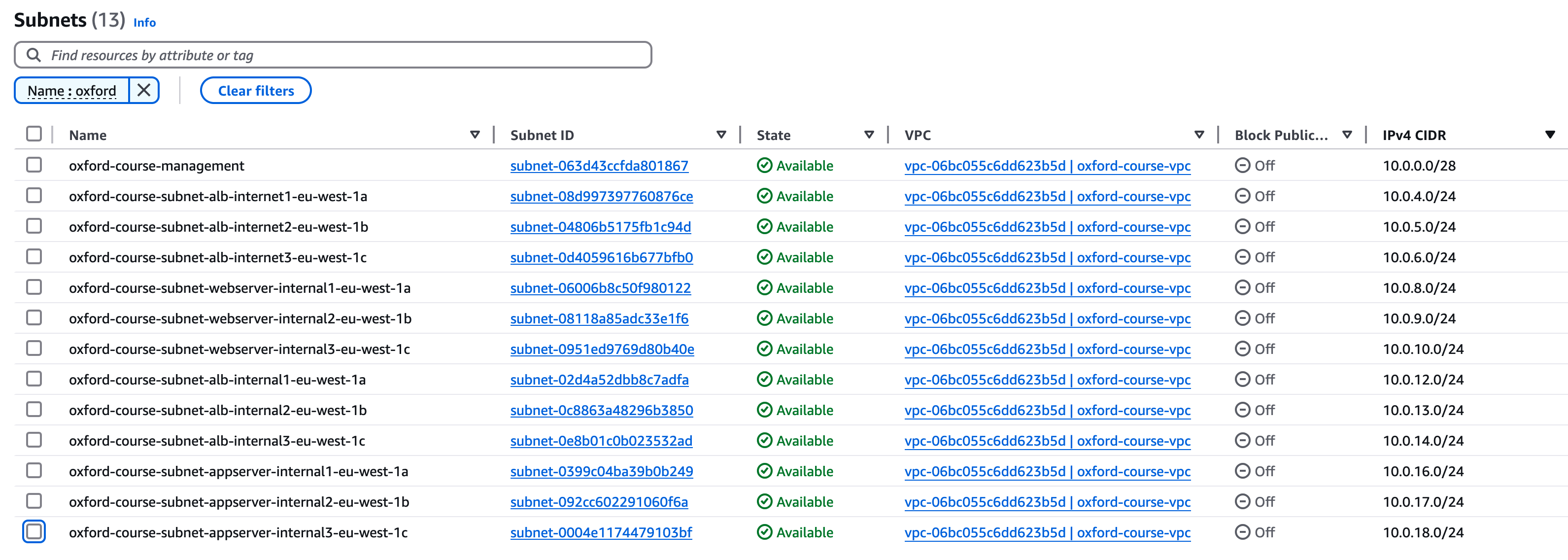
Go to the VPC console and select "Subnets" in the left hand menu. You should see just one entry entry for the management subnet. We are going to create 12 new subnets as follows (the alb in the names standing for application load balancer).
For each subnet select "Create Subnet" then copy the "Subnet name" as below, the "Availability zone" should be as listed and enter the "IPv4 Subnet CIDR block" as listed below, then click "Create subnet"
| Network Range | AZ | Network Name |
|---|
| 10.0.4.0/24 | az-a | oxford-course-subnet-alb-internet1-eu-west-1a |
| 10.0.5.0/24 | az-b | oxford-course-subnet-alb-internet2-eu-west-1b |
| 10.0.6.0/24 | az-c | oxford-course-subnet-alb-internet3-eu-west-1c |
| 10.0.8.0/24 | az-a | oxford-course-subnet-webserver-internal1-eu-west-1a |
| 10.0.9.0/24 | az-b | oxford-course-subnet-webserver-internal2-eu-west-1b |
| 10.0.10.0/24 | az-c | oxford-course-subnet-webserver-internal3-eu-west-1c |
| 10.0.12.0/24 | az-a | oxford-course-subnet-alb-internal1-eu-west-1a |
| 10.0.13.0/24 | az-b | oxford-course-subnet-alb-internal2-eu-west-1b |
| 10.0.14.0/24 | az-c | oxford-course-subnet-alb-internal3-eu-west-1c |
| 10.0.16.0/24 | az-a | oxford-course-subnet-appserver-internal1-eu-west-1a |
| 10.0.17.0/24 | az-b | oxford-course-subnet-appserver-internal2-eu-west-1b |
| 10.0.17.0/24 | az-c | oxford-course-subnet-appserver-internal3-eu-west-1c |
Once you have added these twelve subnets you should find your list of subnets looks like below;
Routing Setup
Having set up the new subnets we now need to set up the route tables to manage how traffic is routed between them. When you create resources such as load balancers in the console the workflow will often offer to create route tables at the same time, but these are generally very open so it is generally best practice to explicitly create the resources we need.
We are going to create Route tables as follows;
| Zone | Route Table Name | Subnets | Description | Routing |
| Internet Facing Load Balancer | oxford-course-rtb-alb-internet | 10.0.4.0/24 AZ A | Subnets for the Internet Facing Load Balancer | Local VPC and Internet Gateway |
| 10.0.5.0/24 AZ B |
| 10.0.6.0/24 AZ C |
| Internet Facing Web Servers | oxford-course-rtb-webserver-internal | 10.0.8.0/24 AZ A | Subnets for the Internet Facing Web Servers | Local VPC only |
| 10.0.9.0/24 AZ B |
| 10.0.10.0/24 AZ C |
| Internal Load Balancer | oxford-course-rtb-alb-internal | 10.0.12.0/24 AZ A | Subnets for the Internal Load Balancer | Local VPC only |
| 10.0.13.0/24 AZ B |
| 10.0.14.0/24 AZ C |
| Application Servers | oxford-course-rtb-appserver-internal | 10.0.16.0/24 AZ A | Subnets for the Internal Load Balancer | Local VPC including the RDS endpoints only |
| 10.0.17.0/24 AZ B |
| 10.0.18.0/24 AZ C |
The first route table we are going to create is for the Internet Facing Application Load Balancer. This will have a route to the Internet Gateway and to the VPC which has the range 10.0.0.0/16.
In the VPC Console, select "Route tables" in the left hand menu
Select "Create route table"
For Name call it "oxford-course-rtb-alb-internet" and for VPC select "oxford-course-vpc". Click "Create route table"
We should see that the Route Table has been created with a default route destination of 10.0.0.0/16 (which represents our entire VPC). We want to add the route to the Internet Gateway so on the routes tab click "Edit routes".
Under destination enter "0.0.0.0/0". For the target choose "Internet Gateway" and in the dropdown select the VPC Internet Gateway which should be of the format "igw-03c245de54f21c2".
This is all we need to do, select "Save changes".
We now need to associate this route table with the subnets for the load balancer. Select the "Subnet associations" tab and click "Edit subnet associations"
This should list the available subnets. In the filter text box enter "alb-internet", this should filter the associations down to the subnets 10.0.4.0/24, 10.0.5.0/24 and 10.0.6.0/24. Select them all with the left hand check boxes and click "Save associations".
We now need to create three route tables for the internal subnets. At this stage all they will have is the default route of 10.0.0.0/16. However, it is still best practice to create different route tables for different layers of the architecture so we can modify them in future with reduced risk of unintended consequences.
Webserver
Select "Create route table"
For Name call it "oxford-course-rtb-webserver-internal" and for VPC select "oxford-course-vpc". Click "Create route table"
We should see that the Route Table has been created with a default route destination of 10.0.0.0/16 (which represents our entire VPC). This is the only route this table needs for now.
This is all we need to do, select "Save changes".
We now need to associate this route table with the subnets for the load balancer. Select the "Subnet associations" tab and click "Edit subnet associations"
This should list the available subnets. In the filter text box enter "webserver", this should filter the associations down to the subnets "10.0.8.0/24", "10.0.9.0/24" and "10.0.10.0/24". Select them all with the left hand check boxes and click "Save associations".
Internal Application Load Balancer
Select "Create route table"
For Name call it "oxford-course-rtb-alb-internal" and for VPC select "oxford-course-vpc". Click "Create route table"
We should see that the Route Table has been created with a default route destination of 10.0.0.0/16 (which represents our entire VPC). This is the only route this table needs for now.
This is all we need to do, select "Save changes".
We now need to associate this route table with the subnets for the load balancer. Select the "Subnet associations" tab and click "Edit subnet associations"
This should list the available subnets. In the filter text box enter "alb-internal", this should filter the associations down to the subnets 10.0.12.0/24, 10.0.13.0/24 and 10.0.14.0/24. Select them all with the left hand check boxes and click "Save associations".
Appserver
Select "Create route table"
For Name call it "oxford-course-rtb-alb-internal" and for VPC select "oxford-course-vpc". Click "Create route table"
We should see that the Route Table has been created with a default route destination of 10.0.0.0/16 (which represents our entire VPC). This is the only route this table needs for now.
This is all we need to do, select "Save changes".
We now need to associate this route table with the subnets for the load balancer. Select the "Subnet associations" tab and click "Edit subnet associations"
This should list the available subnets. In the filter text box enter "appserver", this should filter the associations down to the subnets 10.0.16.0/24, 10.0.17.0/24 and 10.0.18.0/24. Select them all with the left hand check boxes and click "Save associations".
Your route tables should now look like the list below
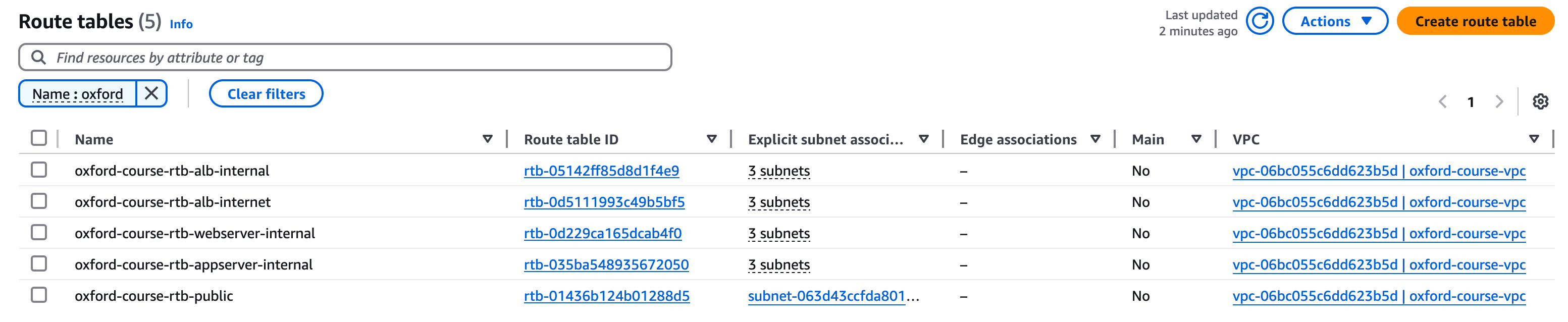
This should be all we need to do for route tables. To review the steps we have taken;
- We have created a new route table for the Internet application load balancer which allows access to the Internet gateway and the hosts in the VPC.
- We have created route tables for the web servers, internal application load balancer and application servers which initially only allow access to the internal VPC.
- We have associated each route table with the corresponding subnets.
Network Testing
Clicking the button below will test your work so far by connecting to your AWS account and testing the VPC setup and the route tables. This gives you the opportunity to check before you complete the next sections.
- Testing VPC Creation
- Testing the Subnet Setup
- Testing Webserver Route Table
- Testing Internal Application Load Balancer Route Table
- Testing Internal Application Server Route Table
Security Group Setup
The final environment setup step we need to take is to set up the security groups for each zone of our application. These allow more granularity in controlling network traffic to each service.
We are going to restruct traffic as follows;
| Zone | Inbound Rules | Outbound Rules |
|---|
| Internet ALB10.0.4.0/22 | Inbound HTTP from anywhere (0.0.0.0/0)Inbound HTTPS from anywhere (0.0.0.0/0) | Outbound HTTP to internal webservers (10.0.8.0/22)Outbound HTTPS to internal webservers (10.0.8.0/22) |
| Internal Webserver10.0.8.0/22 | Inbound HTTP from Internet ALB (10.0.4.0/22)Inbound HTTPS Internet ALB (10.0.4.0/22)Inbound SSH from the bastion network (10.0.0.0/28) | Outbound HTTP to internal ALB (10.0.8.0/22)Outbound HTTPS to anywhere (0.0.0.0/0) |
| Internal ALB10.0.12.0/22 | Inbound HTTP from webservers (10.0.8.0/22)Inbound HTTPS from webservers (10.0.8.0/22) | Outbound HTTP to internal appservers (10.0.16.0/22)Outbound HTTPS to internal appservers (10.0.16.0/22) |
| Internal Appserver10.0.16.0/22 | Inbound HTTP from Internal ALB (10.0.12.0/22)Inbound HTTPS from Internal ALB (10.0.12.0/22)Inbound SSH from the bastion network (10.0.0.0/28) | Outbound HTTPS to anywhere (0.0.0.0/0) |
Note:
There are two entries in bold above for outbound HTTPS access to anywhere. These have been added so that the AWS CLI and API calls work on the servers during setup. In a real production environment if we allowed these calls at all we would use a filtering proxy attached to a dedicated VPC endpoint but now we will make a note of this as a recorded compromise for development.
We are going to create four new security groups as follows;
- oxford-course-sg-internet-alb
- oxford-course-sg-internal-webserver
- oxford-course-sg-internal-alb
- oxford-course-sg-internal-appserver
Security Group 1 - oxford-course-sg-internet-alb
Go to the "EC2 console" and select "Security groups". Select "Create security group".
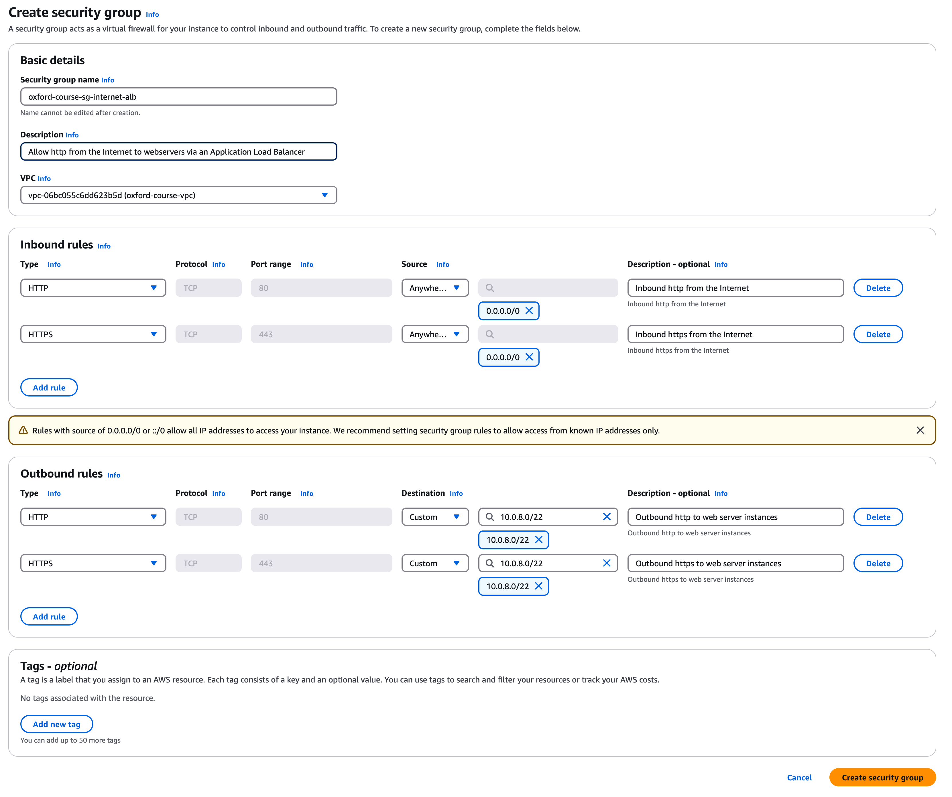
Call the group "oxford-course-sg-internet-alb". For the description enter "Allow http from the Internet to webservers via Application Load Balancer" and select the "oxford-course-vpc" from the VPC drop down.
For the 1st inbound rule select select "http" and source "Anywhere IP V4", description is "Inbound http from the Internet". The console will warn you about accepting traffic from the Internet but this is what the load balancer is designed for.
For the 2nd inbound rule select select "https" and source "Anywhere IP V4", description is "Inbound https from the Internet".
For the 1st outbound rule select "http" but this time for the destination select "Custom" and choose "10.0.8.0/22". This will restrict outbound traffic from the load balancer to the subnets the web servers are in. For description enter "Outbound http to web server instances"
For the 2nd outbound rule select "https" and again for the destination select "Custom" and choose "10.0.8.0/22". For description enter "Outbound https to web server instances"
You do not need to edit any tags.
Finally, click "Create security group". The console will create the security group in about 3 seconds, check the the inbound rules and outbound rules look correct.
Security Group 2 - oxford-course-sg-internal-webserver
For the second security group in the console select "Security groups". Select "Create security group".
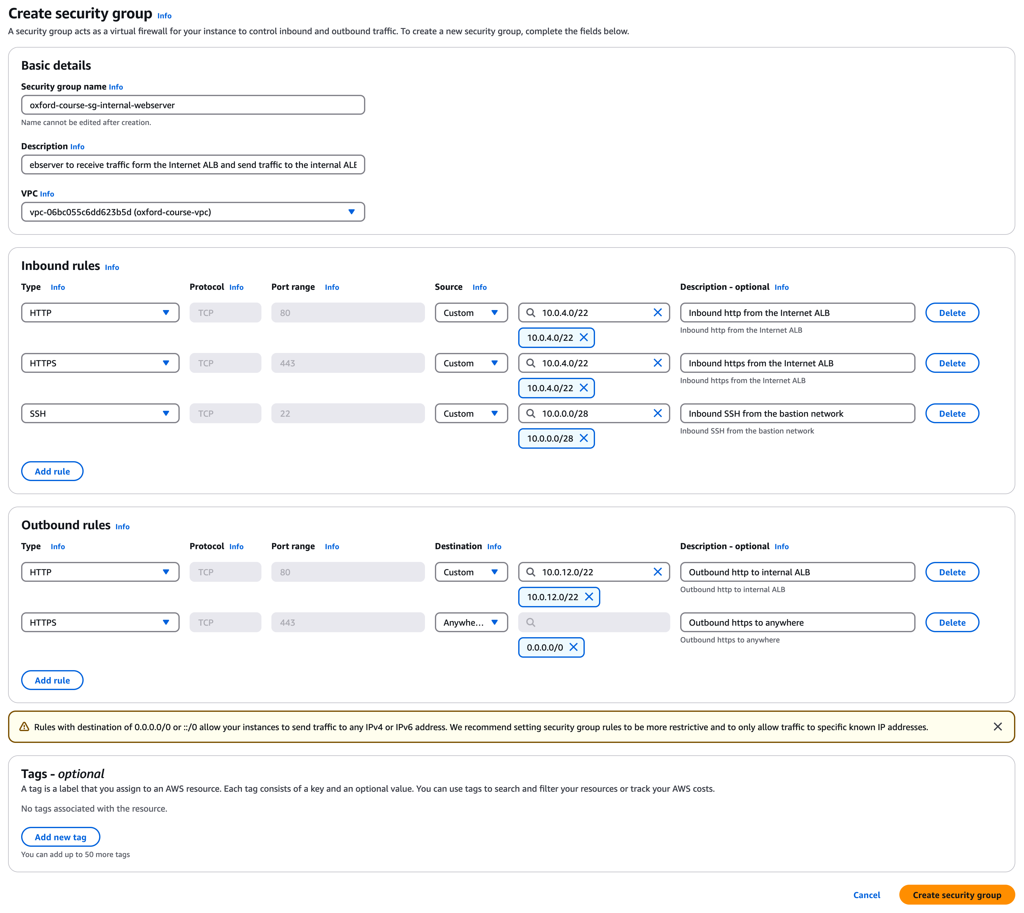
Call the group "oxford-course-sg-internal-webserver". For the description enter "Allow the webserver to receive traffic from the Internet ALB and send traffic to the internal ALB" and select the "oxford-course-vpc" from the VPC drop down.
For the 1st inbound rule select select "http" and source "Custom" and type the IP address range "10.0.4.0/22", description is "Inbound http from the Internet ALB".
For the 2nd inbound rule select select "https" and source "Custom" and type the IP address range "10.0.4.0/22", description is "Inbound https from the Internet ALB".
For the 3rd inbound rule select select "SSH" and source "Custom" and type the IP address range "10.0.0.0/28", description is "Inbound SSH from the bastion network".
For the 1st outbound rule select "http" but this time for the destination select "Custom" and choose "10.0.12.0/22". This will restrict outbound traffic from the load balancer to the internal Application Load Balancer. For description enter "Outbound http to internal ALB"
For the 2nd outbound rule select "https" and for the destination select "Anywhere IP V4" and choose "10.0.8.0/22". For description enter "Outbound https to anywhere"
You do not need to edit any tags.
Finally, click "Create security group".
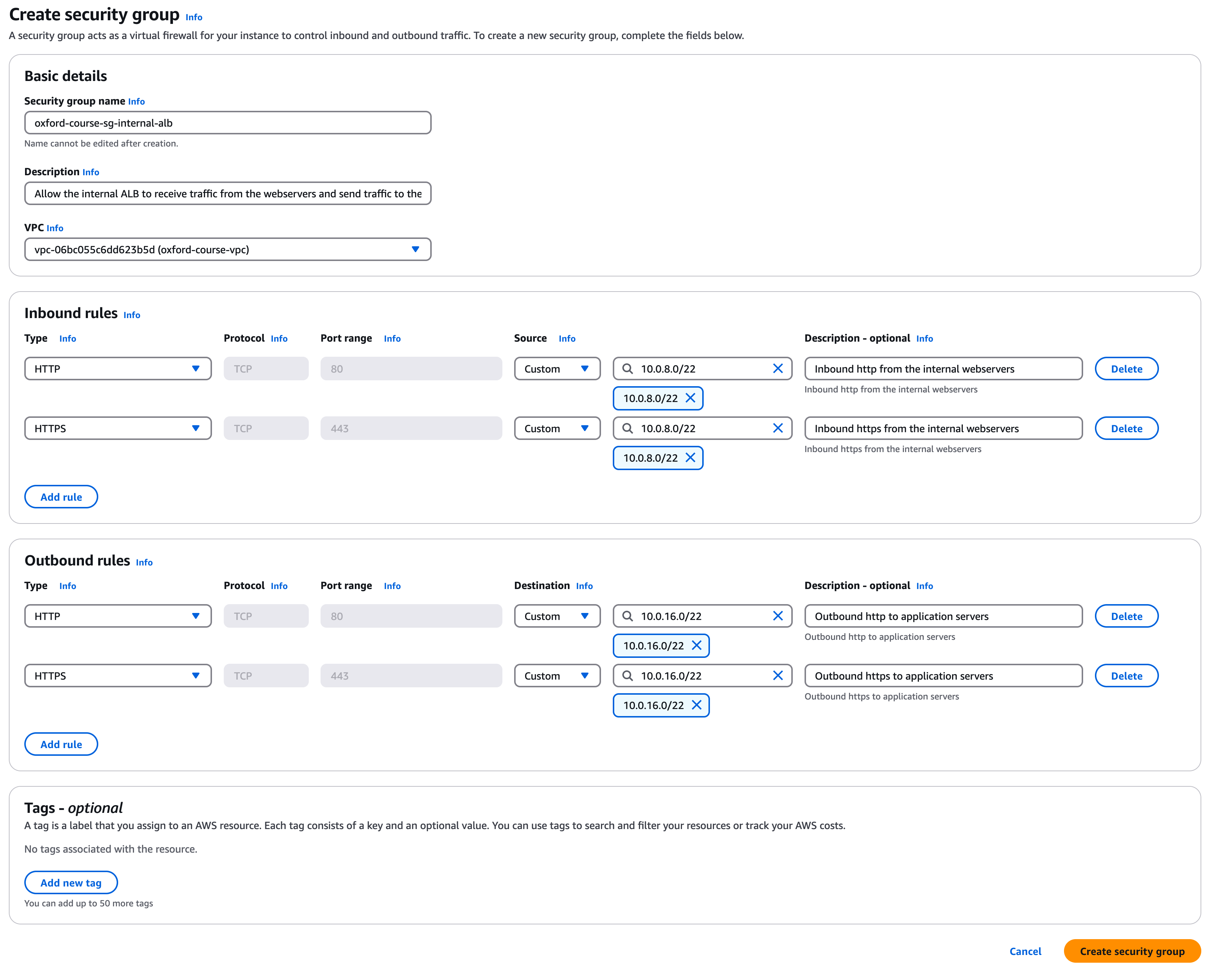
Security Group 3 - oxford-course-sg-internal-alb
For the third security group in the console select "Security groups". Select "Create security group".
Call the group "oxford-course-sg-internal-alb". For the description enter "Allow the internal ALB to receive traffic from the webservers and send traffic to the application servers" and select the "oxford-course-vpc" from the VPC drop down.
For the 1st inbound rule select select "http" and source "Custom" and type the IP address range "10.0.8.0/22", description is "Inbound http from the internal webservers".
For the 2nd inbound rule select select "https" and source "Custom" and type the IP address range "10.0.8.0/22", description is "Inbound https from the internal webservers".
For the 1st outbound rule select "http", for the destination select "Custom" and choose "10.0.16.0/22". This will restrict outbound traffic from the load balancer to the application servers. For description enter "Outbound http to application servers"
For the 2nd outbound rule select "https", for the destination select "Custom" and choose "10.0.16.0/22". For description enter "Outbound https to application servers"
You do not need to edit any tags.
Finally, click "Create security group".
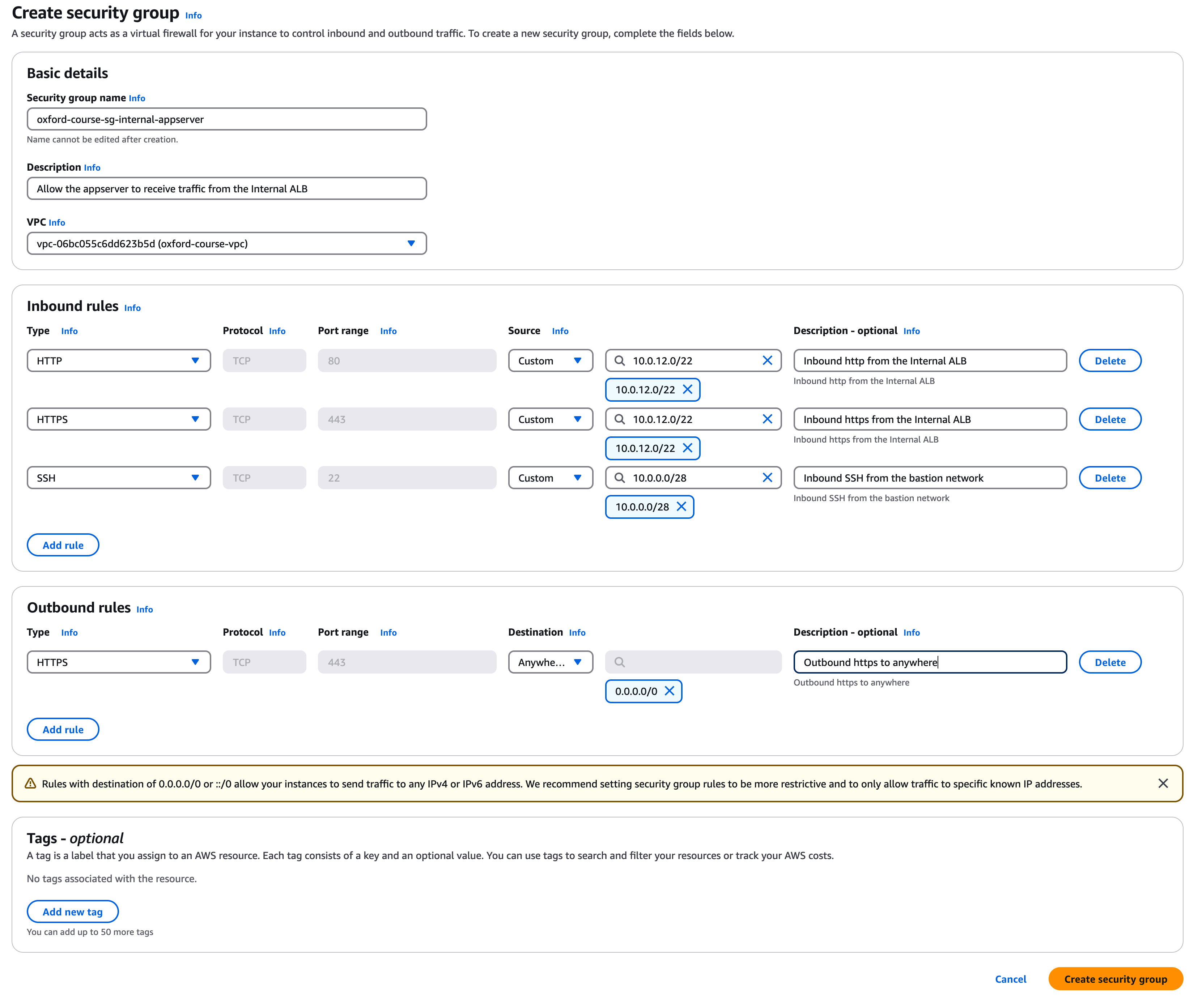
Security Group 4 - oxford-course-sg-internal-appserver
For the second security group in the console select "Security groups". Select "Create security group".
Call the group "oxford-course-sg-internal-appserver". For the description enter "Allow the appserver to receive traffic from the Internal ALB" and select the "oxford-course-vpc" from the VPC drop down.
For the 1st inbound rule select select "http" and source "Custom" and type the IP address range "10.0.12.0/22", description is "Inbound http from the Internal ALB".
For the 2nd inbound rule select select "https" and source "Custom" and type the IP address range "10.0.12.0/22", description is "Inbound https from the Internal ALB".
For the 3rd inbound rule select select "SSH" and source "Custom" and type the IP address range "10.0.0.0/28", description is "Inbound SSH from the bastion network".
For the one outbound rule select "https" and for the destination select "Anywhere IP V4" and choose "10.0.8.0/22". For description enter "Outbound https to anywhere"
You do not need to edit any tags.
Finally, click "Create security group".
Security Group Testing
Clicking the button below will test each of the above security group configurations in your lab.
- Testing Internet Application Load Balancer Security Group
- Testing Internal Web Server Security Group
- Testing Internal Application Load Balancer Security Group
- Testing Internal Application Server Security Group
Setup Summary
It may seem very labour intensive to setup all the environment in this way (and it is) but hopefully it provides the following benefits.
- By mapping an architecture diagram and documented network configuration and security settings to clearly labelled resources with a naming convention it makes it so much easier to debug things when things go wrong. We can very easily see for each zone what the associated security groups, subnets and route tables are simply by searching for the resource names. By having clear CIDR blocks we can map traffic flow and easily debug common issues.
- From a security perspective we have built the basis of a secure architecture. We can see what is facing the Internet and which resources don't have Internet connectivity. Should an instance or zone be compromised there are limits to how far that compromise could laterally spread which aren't present in a flat network structure with open firewall groups.
- Its boring to set things up this way but boredom is good, if you had to do this every time pretty soon any reasonable developer would learn the command line, then start building shell scripts to manage this. After these hit a limit most developer move to Python and Boto and OpenTufu / Terraform templates to build the architectures. But this can't all be taught on day one, its best to understand why things are done a certain way and then optimise how they are delivered.
- If in doubt, ask
Larry Wall
, (
More Larry Wall Quotes
)
We can now take time for coffee and to review the architecture before we start deploying some servers
Console Setup
If you want to use the AWS console, repeat the following step three times to create a webserver in each of the three public VPC subnets
Go to EC2 - Instances then select the "Launch an Instance" Button
For name enter "oxford-course-ec2-ha-webserver" then an instance number 1,2,3 for each instance you launch i.e. "oxford-course-ec2-ha-webserver-1", "oxford-course-ec2-ha-webserver-2", and "oxford-course-ec2-ha-webserver-3"
Under "Application and OS Images (Amazon Machine Image)" click the tab "My AMIs" and "Owned by me". Select the "oxford-webserver-image" we created in lab 1.
For "Instance type" leave as "t2.nano". For "Key pair (login)" choose "OxfordWeb".
For Network settings click "edit" and for each of the three instances we are going to select one of these three public subnets for each instance in turn;
- Instance 1 - oxford-course-subnet-webserver-internal1-eu-west-1a - CIDR 10.0.8.0/24
- Instance 2 - oxford-course-subnet-webserver-internal2-eu-west-2b - CIDR 10.0.9.0/24
- Instance 3 - oxford-course-subnet-webserver-internal3-eu-west-3c - CIDR 10.0.10.0/24
For "auto-assign public IP" this time select "Disable", now we are going to let the outside interface of the load balancer face the public Internet so these instances can manage with private IP addresses
For Firewall (security groups) select "Select existing security group" and select the "oxford-course-sg-internal-webserver"
This should be all we need to edit, select the "Launch instance" button to launch each instance.
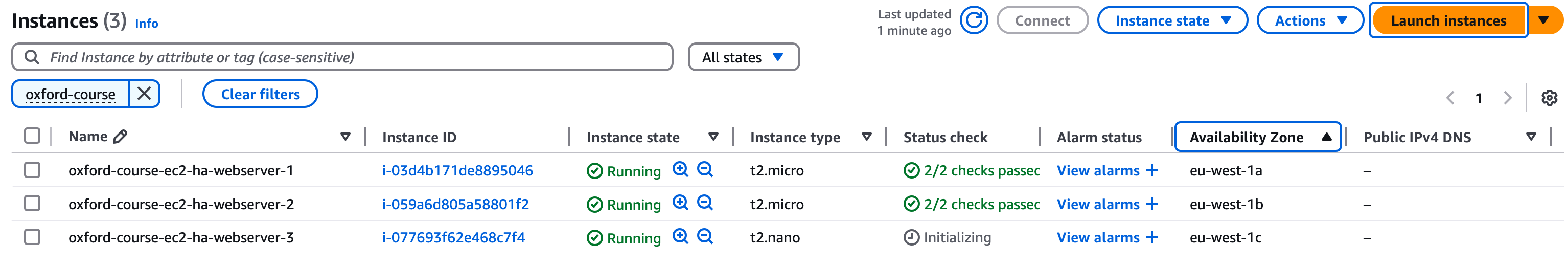
Repeat this process three times for each of the three public subnets, so we have a web server in each availability zone
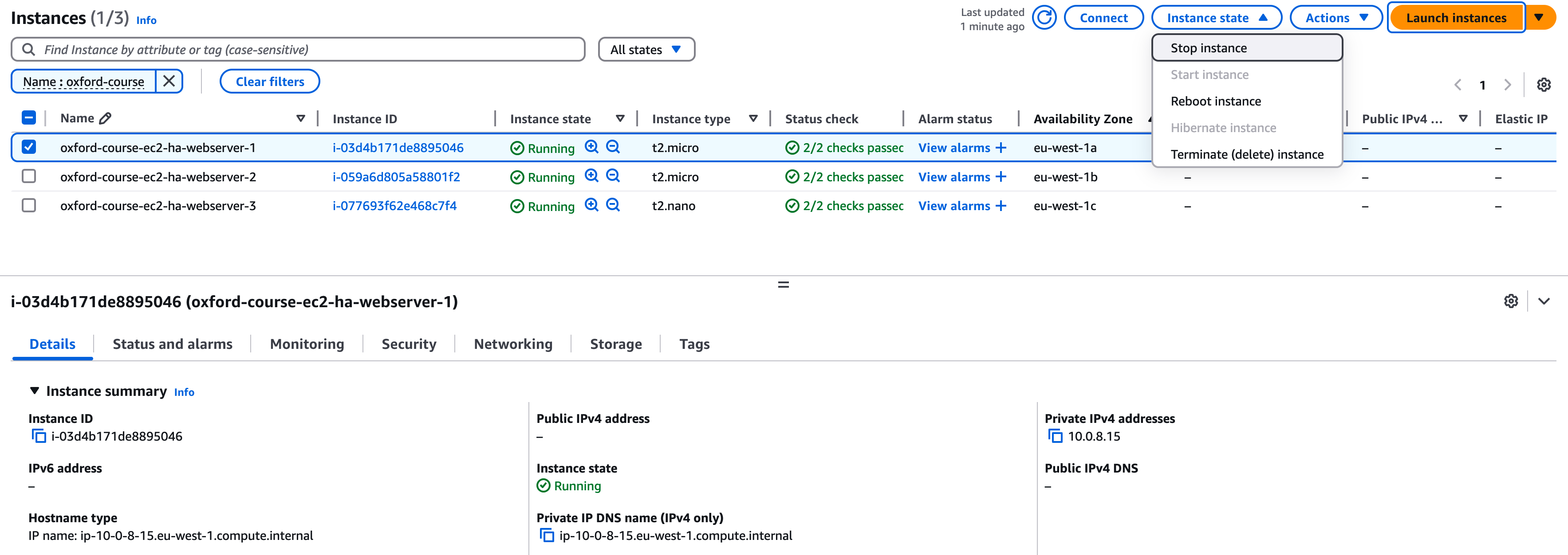
Once you have launch the images, they should look like the below (ignore the instance types, yours should be t2-nano instances)
Target Groups
The first step in setting up our application load balancer in AWS is to set up a target group. This defines which EC2 instances, across multiple availability zones, will be used as we load balance inbound traffic.
Go to the EC2 console and in the left hand menu select "Target Groups" under "Load Balancing"
Choose "Create target group"
Under "Basic configuration", "target type" keep the "target type" as "Instances".
For "Target group name", enter the name "oxford-course-tg-webservers"
Keep the default protocol "(HTTP)" and port "(80)".For the IP address type keep it as "IPv4"
Select the "oxford-course-vpc". Keep the protocol version as "HTTP1".
For Health checks, keep the default settings, protocol should be "HTTP" and Health check path should be "/" .
We don't need to modify anything else so select "Next".
For the "Register Targets" section you should see a list of server instances including the HA Webserver Instances 1, 2 and 3 you just created
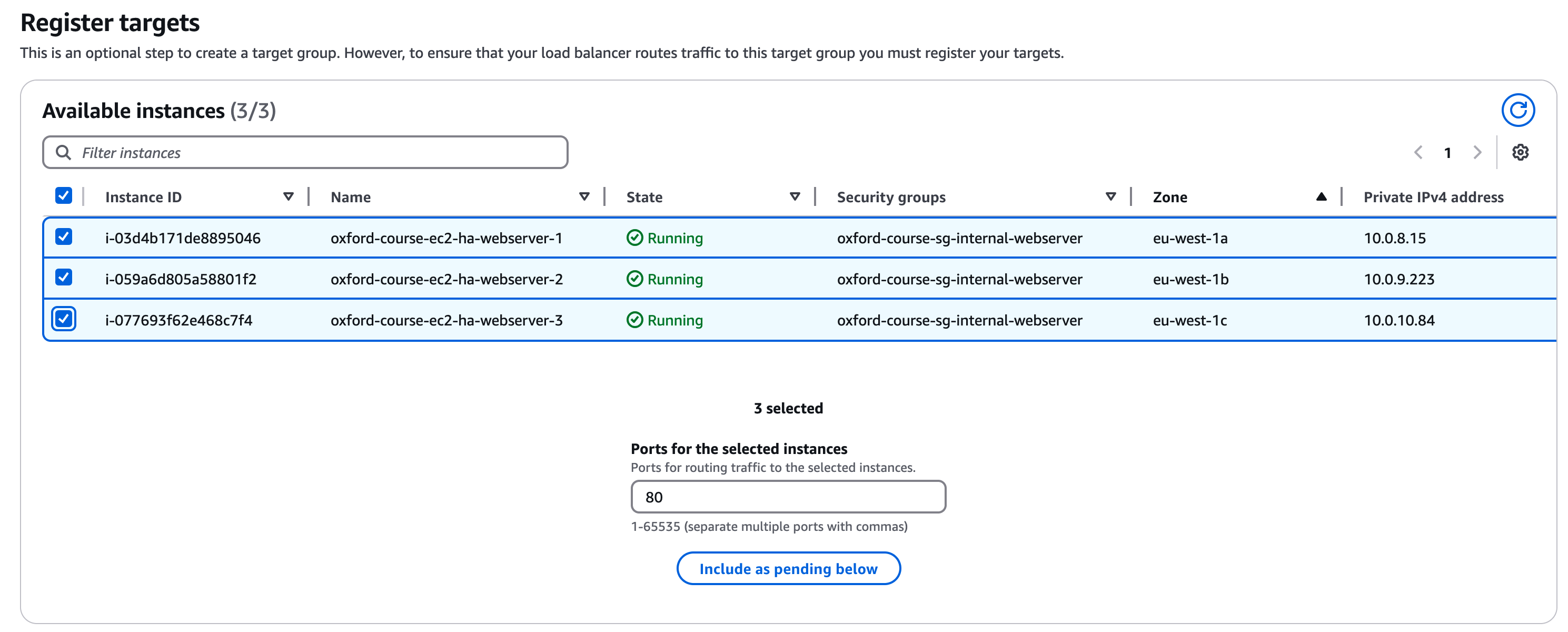
Select all 3 instances, leave the post as Port 80 and click "Include as pending" below
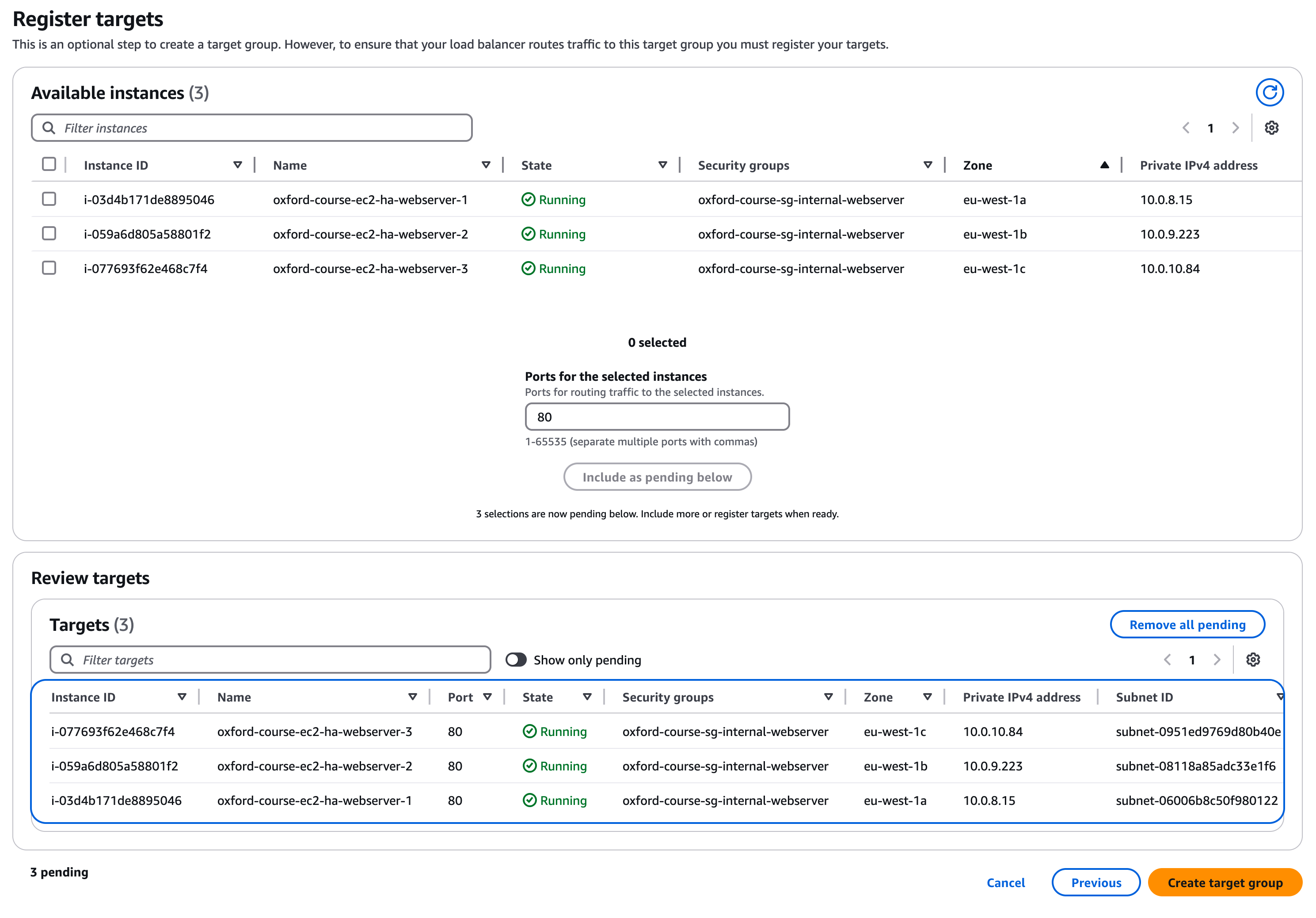
You can now click "Create target group"
You have now created a target group for the load balancer to be associated with, next we need to create the load balancer
Web Server Testing
Clicking the button below will test the web servers and target group in your lab.
- Testing Web Server Configuration
- Testing Web Server Response
- Testing Target Group Setup
Creating an Application Load Balancer
When you create the load balancer, it creates compute instances in each selected availability zone for the load balancer software to run on. AWS takes care of the management and scaling of these instances, but you need to ensure there are subnets for the servers to deploy into. You could deploy into the public subnets we have already created, but we created a new set of subnets for the load balancer. This approach enhances the overall security of the service but also improves overall observability
Go to the EC2 console and in the left hand menu select "Load Balancers" under "Load Balancing"
Choose "Create Load Balancer".
For "Application Load Balancer", choose "Create". We are managing HTTP traffic only to our web application and will be able to take advantage of ALB features such as choosing the destination server based on properties of the HTTP request.
For "Load Balancer Name" enter "oxford-course-alb-internet"
For "Scheme" choose "Internet Facing". The load balancer is going to replace the public IP address on our web server instance as the service which receives Internet traffic. For "Load balancer IP address type" choose "IPV4".
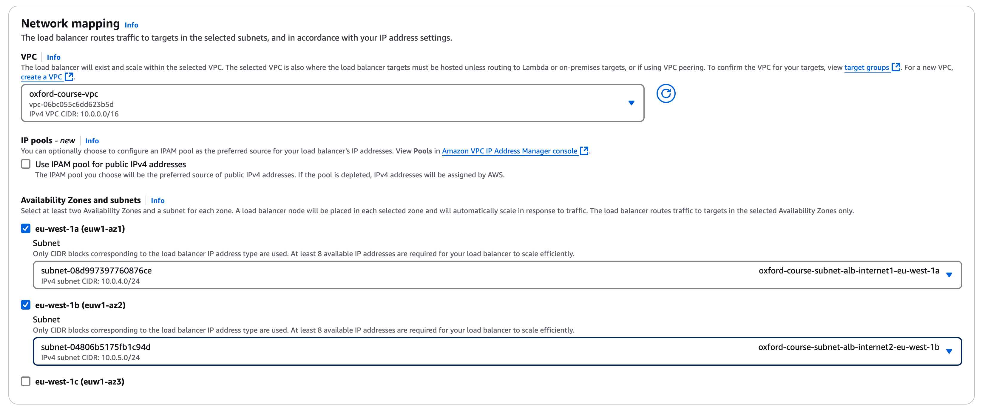
Under "Network mapping" choose the "oxford-course-vpc" under VPC. For mappings you should be presented with three availability zones, select all three of them as we have deployed servers in each AZ, for each AZ selected choose the corresponding public subnet as shown in the list below;
- oxford-course-subnet-alb-internet1-eu-west-1a 10.0.4.0/24
- oxford-course-subnet-alb-internet2-eu-west-1b 10.0.5.0/24
- oxford-course-subnet-alb-internet3-eu-west-1c 10.0.6.0/24
For "Security groups", remove the "default" by clicking on the blue cross next to it and add the "oxford-course-sg-internet-alb" group we created earlier using the drop down (add by selecting the check box in the drop down)
Under "Listeners and routing" we can leave the listener as "HTTP" port "80", we will be load balancing between our web servers running HTTP (port 80) only. For the default action in the "forward to" drop down select the "oxford-course-tg-webservers" group in the drop down.
Click "Create load balancer". You should now see the summary of the new load balancer. The status will be "provisioning", it will take a few minutes for the status to change to "Active" and the DNS name to become available.
Once the load balancer status changes to "Active", under the DNS name you should see a name of the form "oxford-application-load-balancer-272222327.eu-west-1.elb.amazonaws.com (A Record)". Click on the double box icon to copy the public DNS name for the load balancer
Open a new web browser tab or window and paste this address in, then hit "enter"
You should now see our online banking homepage from our first website setup, as below
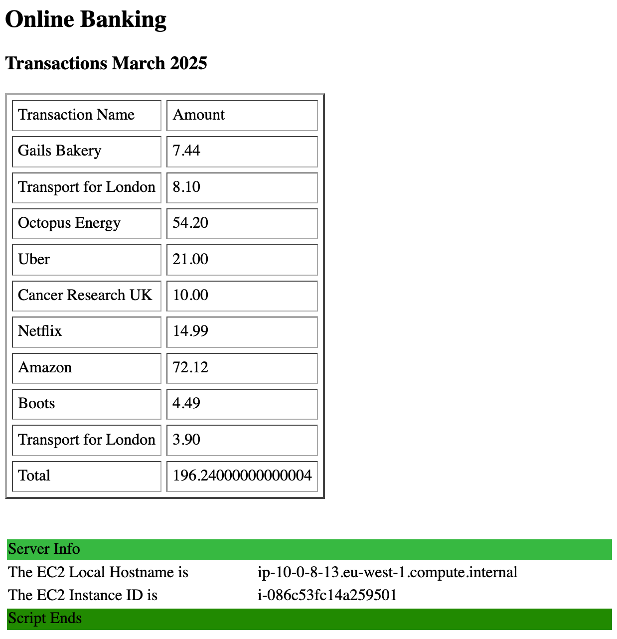
Now hit refresh on the load balancer page. With each refresh you should see that the instance IP addresses cycle through instances in the "10.0.8.0/24", "10.0.9.0/24" and "10.0.10.0/24" network (note our little IP address script changes colours for each instance type to make this more visually obvious)
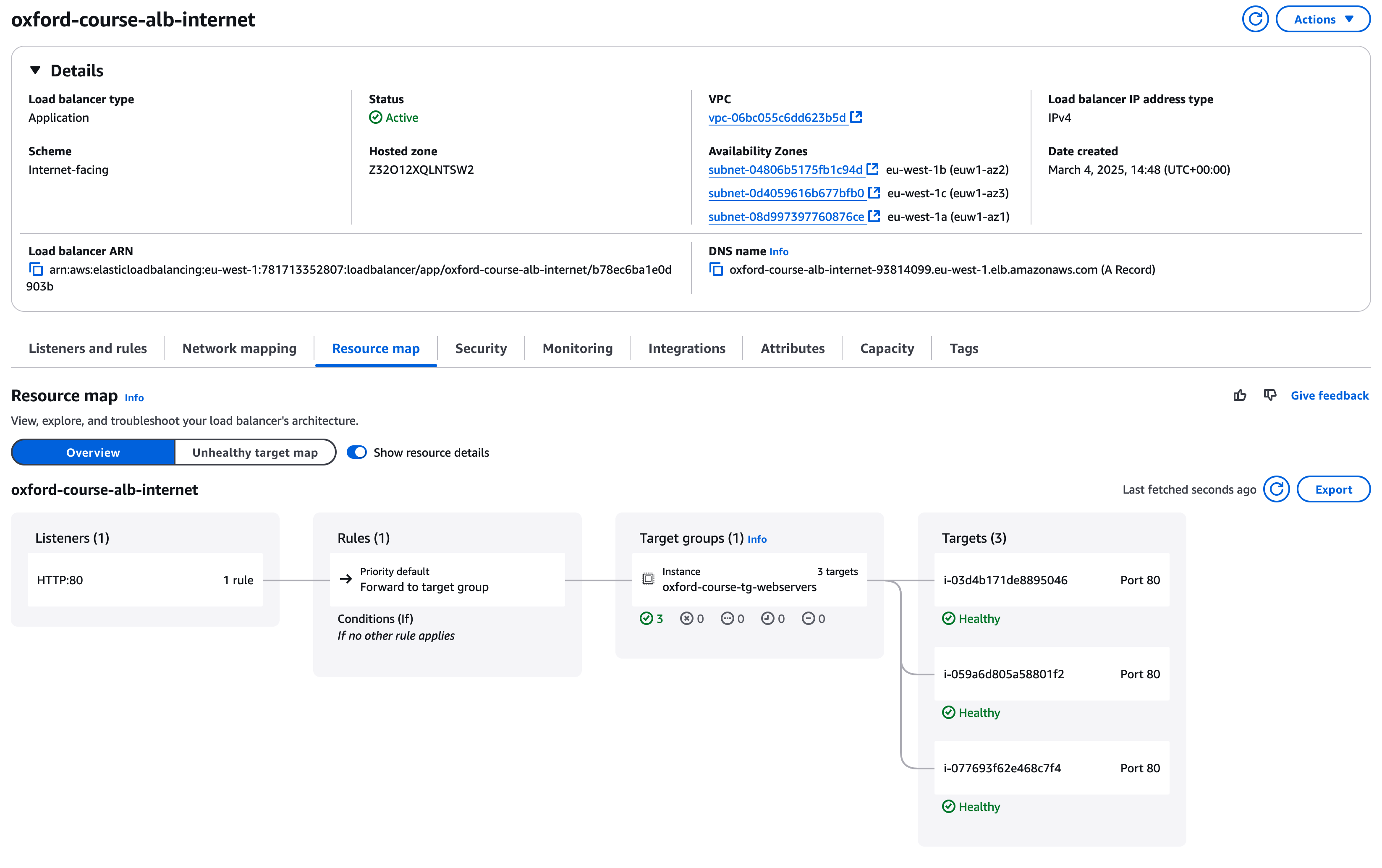
If you go back to the "oxford-course-alb-internet" in the console you can now select the "Resource Map" tab to show how the listener maps to rules which map to the target groups and finally the individual web server instances which are the targets.
A key reason we are looking at load balancers is to enhance our application resiliency if any instance or an availability zone should fail. To demonstrate this we can shut down one of our web server instances and look at how the load balancer manages this
Go to the EC2 console and select "Instances" in the "Instances" menu. You should see HA Webserver Instance 1, 2 and 3 in the list. Select one of them, make a note of their IP address and then select "Stop instance" from the "Instance State" drop down menu on the right of the screen.
Now go back to the "load balancer" tab in your web browser and keep hitting refresh. Rather than cycling through the three web server instances you should see just the two instances are now alternated between, but the page / application continues to be delivered. If you want you can go back and remove one more webserver, you should find as long as one server is available content continues to be delivered.
As you hit refresh you may see a Bad Gateway error as an instance is shutting down but hasn't been removed from the load balancer pool of available instances. There is the risk that a percentage of requests will fail for a few seconds if instances fail, if you need higher availability than this then other architectures may be needed, such as using one or more content delivery networks.
If you now go back to your Load Balancer details page, and look at the resource map, you will now see that under targets one of the instances is now listed as "Unused: Target is in the stopped state"
]
Security Group Testing
Clicking the button below will test the load balancer configuration.
- Testing Load Balancer Configuration
- Testing Load Balancer Response
Load Balancer Summary
So far we have seen how we can use a load balancer to distribute incoming requests across virtual machines in different availability zones / data centres and have them all return core application data. To demonstrate this we have stopped one or more of the instances and shown how health checks on the load balancer have taken it out of service, with traffic being rerouted to the remaining instance(s). This is a good demonstration of how to use load balancers for availability targets to cope with the failure of single elements of the application stack, now we will look at using load balancers for capacity management.
Going back to our architecture diagram, we can now look at how to represent this with the architecture diagram reflecting the load being distributed across the three availability zones.
Clean Up
To get started in this section, delete the Application Load Balancer from the section above along with the Instances and the Target group.
Go to the EC2 console and select "Instances". You can select all the oxford-course Web Server instances and using the "Instance State" menu go ahead and "terminate" them.
Select "Target Groups" under "Load Balancing", select the "oxford-webserver-target" and under the Actions menu select "Delete"
Select "Load Balancers" under "Load Balancing", if the "oxford-application-load-balancer" exists delete it now.
Demonstrating Load Balancers and Auto Scaling
In the previous example we looked at how we can use a load balancer which mirrors a traditional enterprise datacentre load balancer (F5 Big IP devices for example). This is very useful for monitoring the health of target instances and ensuring traffic is balanced to instances which can handle it.
In the Infrastructure as Code world of cloud, we can actually use a load balancer as a key service to provision new resources as demand increases and remove them when demand falls.
This is a relatively complex process so we will do the following and then discuss how each part works. Note each public cloud has slight variations on this functionality but they all follow roughly the same principles.
We will create;
- An "Auto Scaling Group" to manage the rules around the scaling of the web servers.
- A "Target Group" which maps the load balancer to the web server instances
- A new "Load Balancer Service" to manage the traffic and link to scaling events
Note:" In the prior example, we used three Availability Zones (AZs) for the demonstration. For the next section we are going to use 2 AZs only. This would be fine for any site where your availability target was closer to 99.99% than 99.999% and reduces our overall costs.
Creating the Auto Scaling Group
In the EC2 console, go to "Auto Scaling" in the left hand menu and select "Auto Scaling Groups"
The auto scaling page has a good description of how auto scaling works, it is worth taking a minute to read it.
When you are ready Click "Create Auto Scaling group"
For Auto Scaling Group Name call it "oxford-course-asg-internet"
Under launch template click "Create a launch template", this will take us to the "Create Launch Template" workflow.
For the launch template name call it "oxford-course-launch-template-webserver", for the description we can go with "Internet Facing Webserver Launch Template". For auto scaling guidance we should leave this checked, we are going to be using the template with EC2 auto scaling.
For "Application and OS Images (Amazon Machine Image) - required", select the "My AMIs" tab, choose "Owned by me" and select our "oxford-webserver-image" AMI.
For the instance type choose "t2.nano". Not only is this among the cheapest and smallest instance types, for the purposes of this demonstration we should be able to submit enough web requests to push the cpu usage to over the threshold which will then trigger scaling of the group of web server instances.
For key pair login choose "OxfordWeb".
Under Subnet choose "Don't include in launch template". We will specify the subnet details in the auto scaling group.
For "Firewall (security groups)" we can choose "Select existing security group" then in the drop down choose the "oxford-course-sg-internal-webserver" security group.
Finally we can leave the"Storage (volumes)" unchanged at a 8GiB SSD volume.
Click "Create launch template" on the right to save the server launch template
Now we can go back to our "Create Auto Scaling Group" workflow (this may be in a different browser tab). Click the refresh icon next to the "Launch Templates" dropdown, then select our newly created "oxford-internet-webserver-launch-template". If this looks good select "Next".
For step 2 we are going to configure the networks our servers will be deployed into. Choose our "oxford-course-vpc" then for subnets select both "oxford-course-subnet-webserver-internal1-eu-west-1a" and "oxford-course-subnet-webserver-internal2-eu-west-1b". These subnets should have the CIDR ranges "10.0.8.0/24" and "10.0.9.0/24".
"Note - for this exercise we are only deploying instances into 2 availability zones. In practice for a real production application we would normally look to use three availability zones but for this demonstration we are hoping to swamp the webserver instances with traffic so we will use 2 AZs / subnets for now."
For Availability Zone Distribution we will choose "Balanced best effort", this will attempt to launch instance in a working AZ if one AZ becomes unresponsive. Click "Next"
For the next section "integrate with other services - optional" we do not need to change anything. We will add the auto scaling group to the load balancer later. There are some options such as ARC Zonal Shift but they are both very AWS specific and also for niche AWS availability use cases (but do read up on them for real world production deployments). You can click "Next"
Next we configure group size and scaling. For desired capacity we will specify 2 instances, this will mean that one instance launches in each subnet / availability zone we specified.
For scaling we will set "minimum desired capacity" to "2", for "max desired capacity" we will set this to "6". This means we should always have an instance in each availability zone but as we scale up the group can grow to 3 instances in each availability zone. Note that in a real production environment we would probably set a minimum number of 4 instances (they are very small) and scale up to 20 or more, but we are running a demonstration here and trying to be cost conscious.
Under "Automatic scaling", we want the group to change in size depending on overall CPU utilisation. Choose "Target tracking scaling policy" and for Metric type choose "Average CPU utilisation". We can leave the target value at 50 (this is % CPU utilisation across the group) and the Instance warmup at 300 seconds.
For Instance maintenance policy we can leave this as "Mixed Behaviour" "No policy". This is a well tested set of rules for scaling instances based on CPU load or maintenance or availability events. Other options place more emphasis on high availability or cost management.
For additional capacity settings leave this as "default".
For "Additional Settings" we do not need to check these additional options for a simple demo (but again read up on them for a production deployment)
Click "Next"
For the next section "Add notifications", this can be useful, especially when you are using an auto scaling group to replace unhealthy instances or due to Availability Zone failure. However for this demonstration we don't need to enable notifications so we can click "Next"
For "Tags" create a Tag with a "Key" of "Name" and a "value" of "oxford-course-ec2-asg-webserver", ensure "Tag new instances" is "checked". Then click "Next".
We now have a chance to review the Auto Scaling Group. Check that the settings look like the above and, when you are happy, click "Create Auto Scaling group".
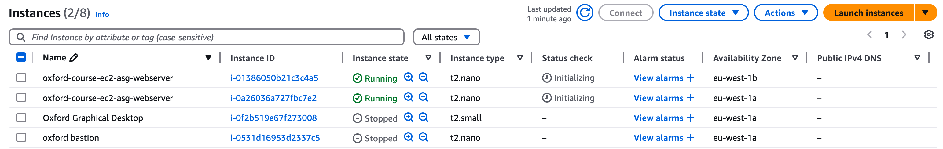
If you go back to the EC2 console page and select Instances you should see that the auto scaling group has launched two instances in Availability Zones "eu-west-1a" and "eu-west-1b" (as shown below)
Creating a New Target Group
Our next step is to recreate the Application Load Balancer and point it to the instances in the Auto Scaling Group
First we need to create the Target Group
Go to the EC2 console and in the left hand menu select "Target Groups" under "Load Balancing"
Choose "Create target group".
Under "Basic configuration","choose a target type" keep the "target type" as "Instances".
For "Target group name", enter the name "oxford-course-tg-webserver"
Keep the default protocol "(HTTP)" and port "(80)".For the IP address type keep it as "IPv4"
Select the "oxford-course-vpc". Keep the protocol version as "HTTP1".
For Health checks, keep the default settings, protocol should be "HTTP" and Health check path should be "/" .
We don't need to modify anything else so select "Next".
For the "Register Targets" section you should see a list of server instances including the two instances launched by the Auto Scaling Group. However, we will link this in a later stage, so for now create the target group without selecting any instances. Without selecting any instances click on "Create target group".
We have now created a target group for the load balancer to be associated with, next we need to recreate the load balancer
Creating a Load Balancer
In the EC2 console go to "Load Balancing" - "Load Balancers".
As before, select "Create Load Balancer" then select "Application Load Balancer"
For "Application Load Balancer", choose "Create". We are managing HTTP traffic only to our web application and will be able to take advantage of ALB features such as choosing the destination server based on properties of the HTTP request.
For "Load Balancer Name" enter "oxford-course-alb-asg" (Oxford Auto Scaling Group Application Load Balancer)
For "Scheme" choose "Internet Facing". The load balancer is going to replace the public IP address on our web server instance as the service which receives Internet traffic. For "Load balancer IP address type" choose "IPV4".
Under "Network mapping" choose the "oxford-course-vpc" under VPC. For mappings you should be presented with three availability zones, select AZ A and AZ B as we set the auto scaling group across two Availability Zones only, for each AZ selected choose the corresponding public subnet "oxford-course-subnet-alb-internet1-eu-west-1a" "10.0.4.0/24" and "oxford-course-subnet-alb-internet2-eu-west-1b" "10.0.5.0/24".
For "Security groups", remove the "default" and add the "oxford-course-sg-internet-alb" group we created earlier using the drop down
Under "Listeners and routing" we can leave the listener as "HTTP" port "80", we will be load balancing between our web servers running HTTP (port 80) only. For the default action in the "forward to" drop down select the "oxford-asg-webserver-target" in the drop down.
Click "Create load balancer". You should now see the summary of the new load balancer. The status will be "provisioning", it will take a few minutes for the service to be fully enabled and the DNS name to become available.
In the details for the new application load balancer, click on "Resource Map". It should look like the image below, note that there are no targets associated with the target group yet.
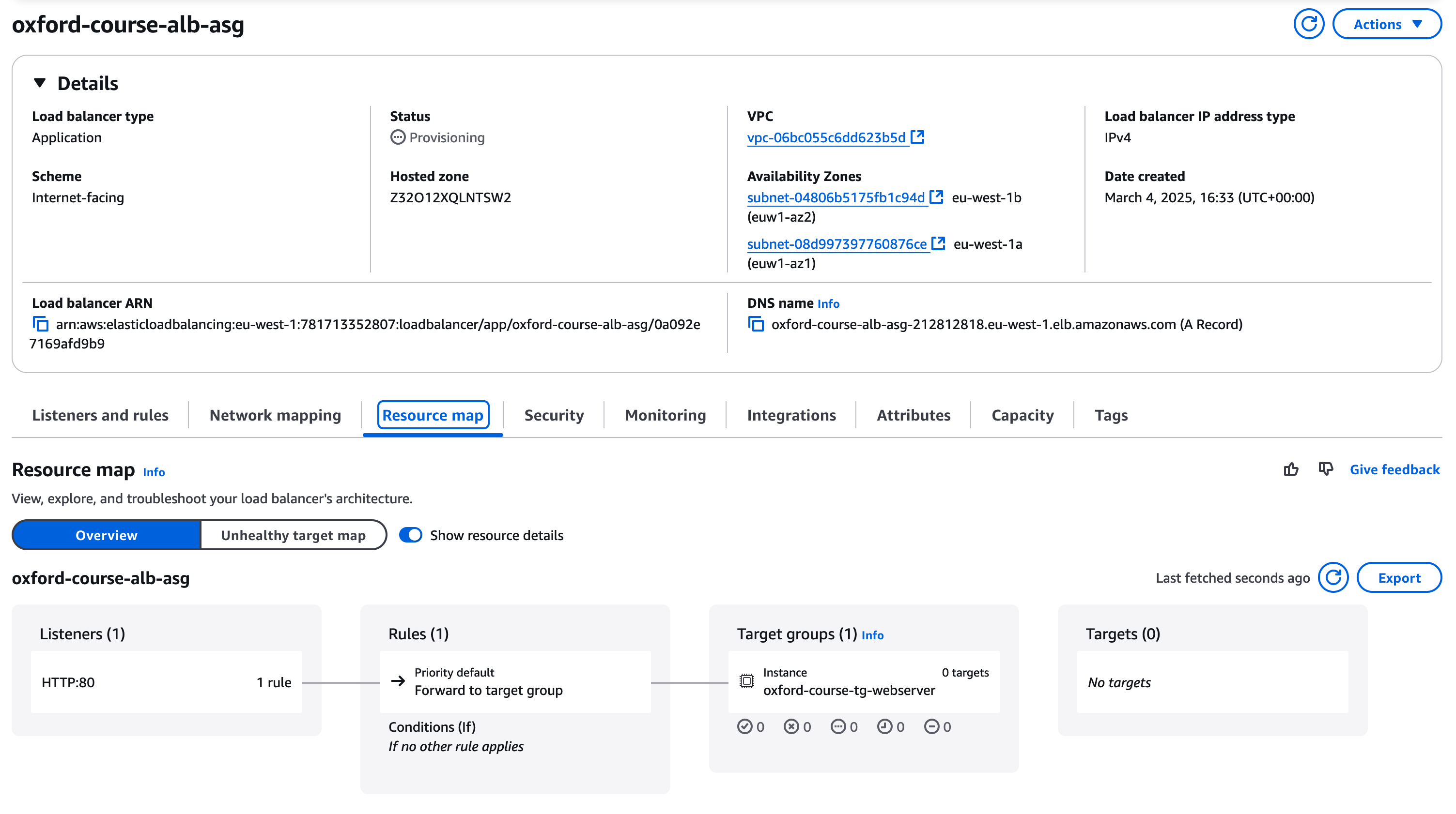
There is one last step to link the Auto Scaling Group to the Load Balancer. In the EC2 console go to Auto Scaling Groups under Auto Scaling. You should see your "oxford-course-asg-internet" group listed.
Select this group with the checkbox and click on the "Integrations - new" tab. Under "Load Balancing" click "Edit".
Check in the dropdown for "Application, Network or Gateway load balancer target groups" then select the "oxford-asg-webserver-target | HTTP" group. Click on "Update" to add the group.
Going back to the Load Balancer, once the load balancer status changes to "Active", under the DNS name you should see a name of the form "oxford-application-load-balancer-272222327.eu-west-1.elb.amazonaws.com (A Record)". Click on the double box icon to copy the public DNS name for the load balancer
Open a new web browser tab or window and paste this address in (selecting http as the protocol e.g. http://(dns name) ), then hit "enter"
You should see the Online Banking page we are very familiar with now. If you keep hitting refresh you should see that the load balancer starts to cycle through the two instances.
Auto Scaling Testing
Clicking the button below will test each of the above security group configurations in your lab.
- Testing Auto Scaling Group
- Testing Target Group Group
- Testing Load Balancer Configuration
- Testing Load Balancer Connectivity
[h1 class="section-heading"]
Testing Capacity
Now we can start testing how the autoscaling group works in practice in conjunction with the load balancer
the first test we can run is to terminate one of our instances. Go to the "EC2 - Instances" page, select one of the two running instances and from the Instance State menu select "Terminate (delete)" instance.
If we go back to our Online Banking homepage and keep clicking refresh now, we will see that the page is only being served from one EC2 instance.
Now go back to the EC2 Instances page, if you look at the list of instances you should see that while one of our instances is terminated there is a new instance, in the same availability zone, in "initializing" state.
If we return to the load balancer / online banking homepage and keep clicking refresh, we will see that quite quickly a new instance has been added to the load balancer. This is because our desired minimum capacity was set to 2 running instances so the auto scaling group will add instances until the minimum number is met.
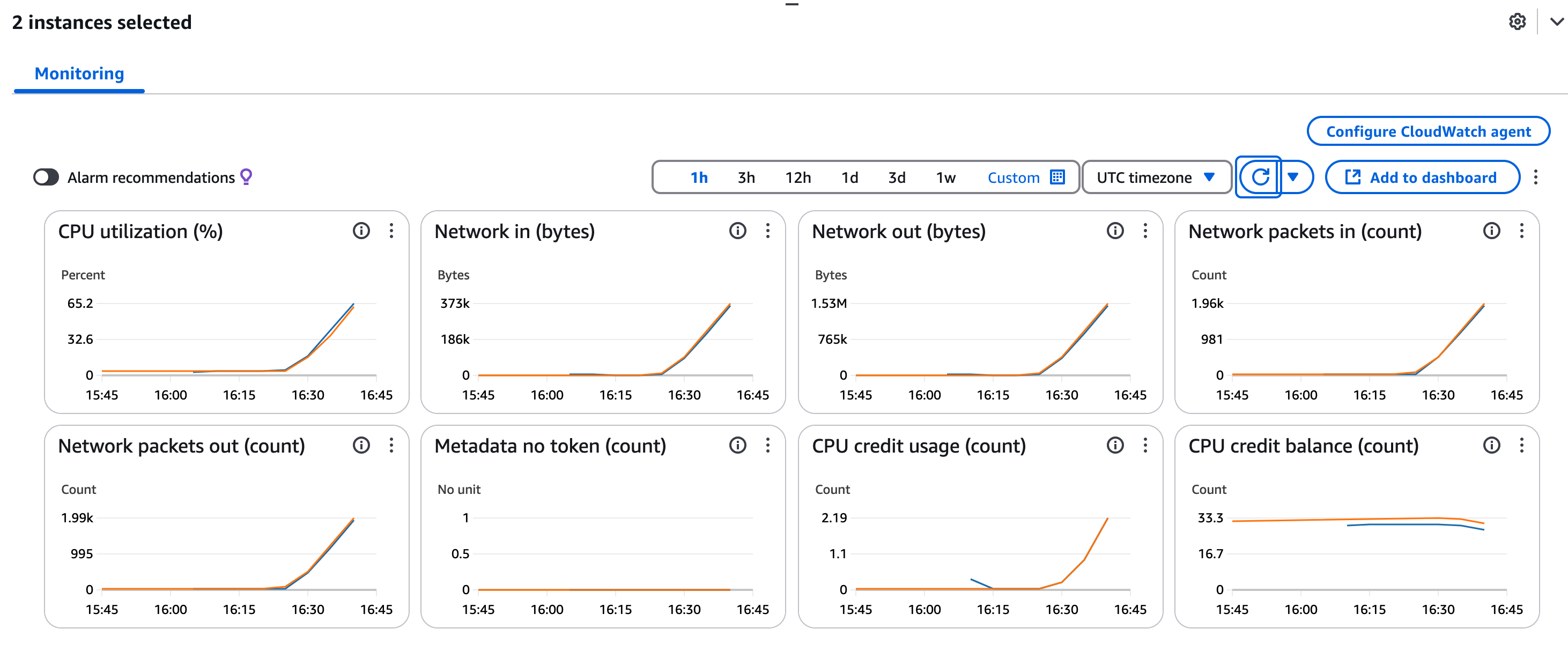
We will now look at how the group scales under load.
You could download a tool like httpdperf or bombarder. However in practice these are very small instances and you should be able to overload them using an endless curl command loop, e.g. (replacing the DNS name with the name of your Application Load Balancer)
while true; do curl http://"oxford-asg-alb-738529061.eu-west-1.elb.amazonaws.com"/; done
"Note", replacing the load balancer host name in the example above with your own load balancer DNS name.
Running 7 instances of this loop should be enough to trigger the creation of a new server instance
Once another server has been triggered, kill off your load generating commands and you should see 10 - 15 minutes later the pool will reduce the number of servers to 2.
(useful bonus article - https://aws.amazon.com/blogs/networking-and-content-delivery/scaling-strategies-for-elastic-load-balancing/).
[h1 class="section-heading"]
Application Server Load Balancer
For this section we are going ask you to deploy a second application load balancer as an internal load balancer in front of the "application" servers which are accessed from the web servers.
You are going to do the following
Deploy the application server instances manually as we did in the first exercise, use the application server AMI and deploy into the networks "10.0.16.0/24", "10.0.17.0/24", try to follow the naming convention of the other components of the architecture.
WNext create an "Load Balancer Target Group" for these servers, follow the same steps as the first exercise and give it the name "oxford-course-tg-appservers"
Deploy an Internal Application Load Balancer across the two networks "10.0.12.0/24", "10.0.13.0/24". Unlike the Internet facing Application Load Balancer deployed above this should be when you select a "Scheme" this should be "Internal". Choose the "oxford-course-vpc" and select these two networks from Availability zones eu-west-1a and eu-west-1b.
For the security group for the Internal ALB choose "oxford-course-sg-internal-alb"
For "Listeners and routing" leave as HTTP 80 and select the target group you just created i.e. "oxford-course-tg-appservers"
Click "Create load balancer" and the load balancer should start to initialise
We can't access the load balancer directly so we need to log in to the web servers to test access and reconfigure the web server to point to the application server
If your bastion server isn't running restart it and make a note of its public IP address, then find the web server running in the network 10.0.8.0/24 and make a note of its internal IP address
On your laptop edit your .ssh/config file to update the IP addresses in bold respectively
Host bastion
    User ec2-user
    HostName [strong]
3.255.107.52[/strong]

    Port 22
    IdentityFile ~/keys/OxfordBastion.pem

Host web
    User ec2-user
    HostName [strong]
10.0.8.183[/strong]

    Port 22
    IdentityFile ~/keys/OxfordWeb.pem
    ProxyJump bastion
(adjust accordingly if you are using Windows)
From the webserver check you can access the application servers as we did on day one by using "curl http://(internal ALB dns name)/cgi-bin/transactions.py" and then "url http://(internal ALB dns name)/cgi-bin/transactions.py".
If you have issues try the following
Route tables. All internal subnets should have a route to anything in the VPC which is 10.0.0.0/16, check that every subnet is at least associated with a route table which provides this.
Security Groups - Check the inbound and outbound connection rules for each layer of the application. Try to resist the temptation to just put wildcards in to make everything work but debug the webserver accepting connections from the internet facing application load balancer (10.0.4.0/22) and out to the internal load balancer (10.0.12.0/22) the internal load balancer accepting connections over http from the webserver networks (10.0.8.0/22) and making them out to the application server (10.0.16.0/22) and the application server only accepting connection from the load balancer in the 10.0.12.0/22 range (double check with the table at the start of this page)
If everything works you can update your web server home page to point to the application server as follows, replacing "(DNS Name for Internal ALB)" with the actual DNS name for the internal ALB.
<HTML>
        <HEAD>
                <TITLE>CLO - Internet Banking Test Site</TITLE>
        </HEAD>
        <BODY>
                <H2>Online Banking</H2>
                <H3>Transactions March 2025</H3>
                <TABLE BORDER=2 CELLSPACING=5 CELLPADDING=5>
                        <TR>
                                <TD>Transaction Name</TD><TD>Amount</TD>
                                <!--#exec cmd="curl http://(DNS Name for Internal ALB)/cgi-bin/transactions.py" -->
                        </TR>
                </TABLE>
                <!--#include virtual="/cgi-bin/hostname.sh"-->
                <!--#exec cmd="curl http://(DNS Name for Internal ALB)/cgi-bin/hostname.sh"-->
        </BODY>
</HTML>
If all has gone well you should see that when you reload the homepage and cycle through the instances as you hit refresh, when the load balancer hits this instance the transaction list is served from the application server and you see the hostname details for both the local web and remote application server.
The last thing to do is to apply this change to every server instance, and using our launch template this is surprisingly easy
Carry out the following;
- Save an AMI image from the EC2 console of the webserver you were just working on (in the 10.0.8.0/24 network), call it something like "oxford-course-ami-abl-webserver"
- Go to "EC2 - Instances - Launch Template" and edit the template "oxford-course-launch-template-webserver". Select "Modify Template (Create new version)" in the actions menu. Give it the same name as before but update the AMI to the version you just created, everything else should remin the same
- Now in the "action menu" set this version 2 to be the default version
- Now go to the EC2 instances menu. Select the "oxford-course-ec2-asg-webserver" instance you didn't modify, it should be the one running in AZ "eu-west-1b". Terminate this instance.
- After a minute or so you should see the auto scaling groups has launched a new instance. However, this time it has used to updated launch template and launched the new server version. Until the template is modified this will be the version which is launched.
- Once the new server is up, if you cycle through the instances in your web browser you will see they are always served from the web and application server.
End of lab clean up
Once this lab is completed, you can delete the environment.
It is worth noting that to clean the environment up we can't just terminate instances any more, as the auto scaling group will just replace them.
Therefore we will delete services in this order
Go to "Autoscaling and Auto Scaling Groups", select the group and under actions select "delete". It will warn you that this will terminate all the instances in the group, type "delete" to confirm and the group will be deleted.
Next go to "Load Balancers", select the load balancer and actions "Delete Load Balancer", type "confirm" to confirm and then the load balancer will be deleted.
Go to "Instances" - "Launch Templates" and "Delete" the Launch templates we created
Finally just for clean up we can go to "Load Balancing" - "Target Groups", select the target groups and under actions select "Delete" and confirm.
Note that sometimes the instances seemed very slow to terminate when the auto scaling group was deleted, so it is recommended to terminated them manually from the Instances page of the EC2 console
You should be safe to terminate all the instances in the environment now (apart from the Bastion, which we can stop if you wish to use it in another lab), this will reduce their storage costs.
This concludes this lab.